Nu ik min of meer heb uitgezocht hoe het baantje is opgebouwd, wilde ik eens kijken of ik zelf iets kon toevoegen. Een sein leek mij wel een aardige oefening. Maar …. dat is zo 1-2-3 niet gedaan!
Om een sein (of wissel, of iets soortgelijks) aan te sturen moet er iets tussen de CS2 en het sein zitten: iets wat het signaal oppikt en doorgeeft aan het juiste sein.
Op de modelbaan zijn de twee K83-wisseldecoders daar om het signaal voor de aangesloten 2×4 wissels aan te sturen (zie ook Deel 3a – Wissels). Om meer aan te sturen zouden er dus meer K83-modules aangesloten moeten worden, of … een paar Arduino’s! Dat gaat als volgt.
Over de twee signaaldraden vanuit de CS2 gaan de opdrachten voor locomotieven, wissels, seinen e.d. De spanning op dat aderpaar is ca. 18V. De Arduino kan daar niet echt tegen, dus moet het signaal “losgekoppeld” worden van die 18V. Daarvoor zorgt onderstaande schakeling: een DCC naar Arduino omzetter.

Op de uitgang staat het uitgefilterde signaal dat op pin 2 van de Arduino wordt aangeboden.


Een oude bekende van mij heeft hiervoor een mooie Arduino sketch gefabriceerd: de sketch staat hieronder. Bron: Fun with Arduino – part 29.
//////////////////////////////////////////////////////////////////////////////////////////////////////////////////////
// DCC Accessory / Function Decoder
// Author: Ruud Boer - September 2015
// This sketch turns an Arduino into a DCC decoder with max 17 function outputs.
// Output pins used: 3-19 (14-19 = A0-A5). Pin becomes LOW when accessory is switched ON
// Modes: 1-continuous, 2=oneshot, 3=flasher with 2 alternatin outputs, 4=signal with 2 inverted outputs
// The DCC signal is fed to pin 2 (=Interrupt 0).
// Optocoupler schematics for DCC to 5V conversion: www.rudysmodelrailway.wordpress.com/software
// Many thanks to www.mynabay.com for publishing their DCC monitor and -decoder code.
//////////////////////////////////////////////////////////////////////////////////////////////////////////////////////

//////////////////////////////////////////////////////////////////////////////////////////////////////////////////////
// IMPORTANT: GOTO lines 20 and 43 to configure some data!
//////////////////////////////////////////////////////////////////////////////////////////////////////////////////////

#include <DCC_Decoder.h>
#define kDCC_INTERRUPT 0

//////////////////////////////////////////////////////////////////////////////////////////////////////////////////////
// Fill in the number of accessories / functions you want to control
//////////////////////////////////////////////////////////////////////////////////////////////////////////////////////
const byte maxaccessories = 4;
//////////////////////////////////////////////////////////////////////////////////////////////////////////////////////

typedef struct {
  int               address;          // User Configurable. DCC address to respond to
  byte              mode;             // User Configurable. Mode: 1=Continuous, 2=Oneshot, 3=Flasher
  byte              outputPin;        // User Configurable. Arduino pin where accessory is connected to
  byte              outputPin2;       // User Configurable. 2nd pin for AlternatingFlasher (e.g. railway crossing)
  int               ontime;           // User Configurable. Oneshot or Flasher on time in ms
  int               offtime;          // User Configurable. Flasher off time in ms
  byte              onoff;            // User Configurable. Initial state of accessory output: 1=on, 0=off (ON = pin LOW)
  byte              onoff2;           // User Configurable. Initial  state of 2nd output: 1=on, 0=off
  byte              dccstate;         // Internal use. DCC state of accessory: 1=on, 0=off
  byte              finished;         // Internal use. Memory that says the Oneshot is finished
  unsigned long     onMilli;          // Internal use.
  unsigned long     offMilli;         // Internal use.
}
DCCAccessoryAddress;
DCCAccessoryAddress accessory[maxaccessories];

//////////////////////////////////////////////////////////////////////////////////////////////////////////////////////
// Fill in the attributes for every accessory / function
// COPY - PASTE as many times as you have functions. The amount must be same as in line 18 above!
//
//
//
//////////////////////////////////////////////////////////////////////////////////////////////////////////////////////
void ConfigureDecoderFunctions() // The amount of accessories must be same as in line 26 above!
{
  accessory[0].address = 20; // DCC address
  accessory[0].mode = 1; // Continuous: HIGH until DCC switches the address off again
  accessory[0].outputPin = 3; // Arduino pin to which this accessory is connected

  accessory[1].address = 21;
  accessory[1].mode = 2; // Oneshot: HIGH for ontime ms, then LOW and stays LOW.
  accessory[1].outputPin = 4;
  accessory[1].ontime = 1000;

  accessory[2].address = 22;
  accessory[2].mode = 3; // Flasher: HIGH for ontime ms, LOW for offtime ms, repeats till DCC off
  accessory[2].outputPin = 5;
  accessory[2].outputPin2 = 6; // Flasher can use 2 outputs, they will flash  on/off alternatively
  accessory[2].ontime = 500;
  accessory[2].offtime = 500;

  accessory[3].address = 23; // DCC address
  accessory[3].mode = 4; // Continuous: HIGH until DCC switches the address off again
  accessory[3].outputPin = 7; // Green signal
  accessory[3].outputPin2 = 8; // Red Signal
  accessory[3].onoff2 = 1; // Initially set Red signal to ON

}  // END ConfigureDecoderFunctions

  //////////////////////////////////////////////////////////////////////////////////////////////////////////////////////
  // DCC accessory packet handler
  //////////////////////////////////////////////////////////////////////////////////////////////////////////////////////
  void BasicAccDecoderPacket_Handler(int address, boolean activate, byte data)
  {
    // Convert NMRA packet address format to human address
    address -= 1;
    address *= 4;
    address += 1;
    address += (data & 0x06) >> 1;

    boolean enable = (data & 0x01) ? 1 : 0;

    for (int i=0; i<maxaccessories; i++)
    {
      if (address == accessory[i].address)
      {
        if (enable) accessory[i].dccstate = 1;
        else accessory[i].dccstate = 0;
      }
    }
  } //END BasicAccDecoderPacket_Handler

//////////////////////////////////////////////////////////////////////////////////////////////////////////////////////
// Setup (run once)
//////////////////////////////////////////////////////////////////////////////////////////////////////////////////////
void setup()
{
  ConfigureDecoderFunctions();
  DCC.SetBasicAccessoryDecoderPacketHandler(BasicAccDecoderPacket_Handler, true);
  DCC.SetupDecoder( 0x00, 0x00, kDCC_INTERRUPT );
  pinMode(2,INPUT_PULLUP); // Interrupt 0 with internal pull up resistor (can get rid of external 10k)

  for(int i=3; i<20; i++)
  {
    pinMode(i, OUTPUT);
    digitalWrite(i, HIGH); //all function outputs are set to 0 at startup
  }
} // END setup

//////////////////////////////////////////////////////////////////////////////////////////////////////////////////////
// Main loop (run continuous)
//////////////////////////////////////////////////////////////////////////////////////////////////////////////////////
void loop()
{
  static int addr = 0;

  DCC.loop(); // Loop DCC library

  if( ++addr >= maxaccessories ) addr = 0; // Next address to test

  if (accessory[addr].dccstate)
  {
    switch (accessory[addr].mode)
    {
    case 1: // Continuous
      accessory[addr].onoff = 1;
      break;
    case 2: // Oneshot
      if (!accessory[addr].onoff && !accessory[addr].finished)
      {
        accessory[addr].onoff = 1;
        accessory[addr].offMilli = millis() + accessory[addr].ontime;
      }
      if (accessory[addr].onoff && millis() > accessory[addr].offMilli)
      {
        accessory[addr].onoff = 0;
        accessory[addr].finished = true; //this is reset to flase below in the 'else' statement
      }
      break;
    case 3: // Flasher, is always an 'alternating' flasher together with .outputPin2
      if (!accessory[addr].onoff && millis() > accessory[addr].onMilli)
      {
        accessory[addr].onoff = 1;
        accessory[addr].onoff2 = 0;
        accessory[addr].offMilli = millis() + accessory[addr].ontime;
      }
      if (accessory[addr].onoff && millis() > accessory[addr].offMilli)
      {
        accessory[addr].onoff = 0;
        accessory[addr].onoff2 = 1;
        accessory[addr].onMilli = millis() + accessory[addr].offtime;
      }
      break;
    case 4: // Signal
      accessory[addr].onoff = 1;
      accessory[addr].onoff2 = 0;
      break;
    }
  }
  else //accessory[addr].dccstate == 0
  {
    accessory[addr].onoff = 0;
    if (accessory[addr].mode == 4) accessory[addr].onoff2 = 1; else accessory[addr].onoff2 = 0;
    if (accessory[addr].mode == 2) accessory[addr].finished = false; // Oneshot finished by DCCstate, not by ontime
  }

  // activate outputpin, based on value of onoff
  if (accessory[addr].onoff) digitalWrite(accessory[addr].outputPin, LOW);
  else digitalWrite(accessory[addr].outputPin, HIGH);
  if (accessory[addr].onoff2) digitalWrite(accessory[addr].outputPin2, LOW);
  else digitalWrite(accessory[addr].outputPin2, HIGH);

} //END loop
Per Arduino zal de sketch aangepast moeten worden, afhankelijk van het aantal en de functie van de accessories die aangesloten worden.
- In regel 22 moet aangegeven worden hoeveel “accessories” er aangesloten zijn.
- In de functie ConfigureDecoderFunctions() (vanaf regel 46) moet per accessory aangegeven worden: het adres, wat voor actie er moet volgen en op welke pin de accessory zit.
- Voor de acties zijn 4 opties:
– mode =1; // Continuous: HIGH until DCC switches the address off again
– mode =2; // Oneshot: HIGH for ontime ms, then LOW and stays LOW
– mode =3; // Flasher: HIGH for ontime ms, LOW for offtime ms, repeats till DCC off
– mode =4; // Continuous: HIGH until DCC switches the address off again
Voor de test zijn in bovenstaande sketch zijn 4 accessories aangemaakt, van elke ‘smaak’ een, met de adressen 20 t/m 23.
Ook voor de test heb ik in CS2 een sein aangemaakt: sg2: zie hieronder.
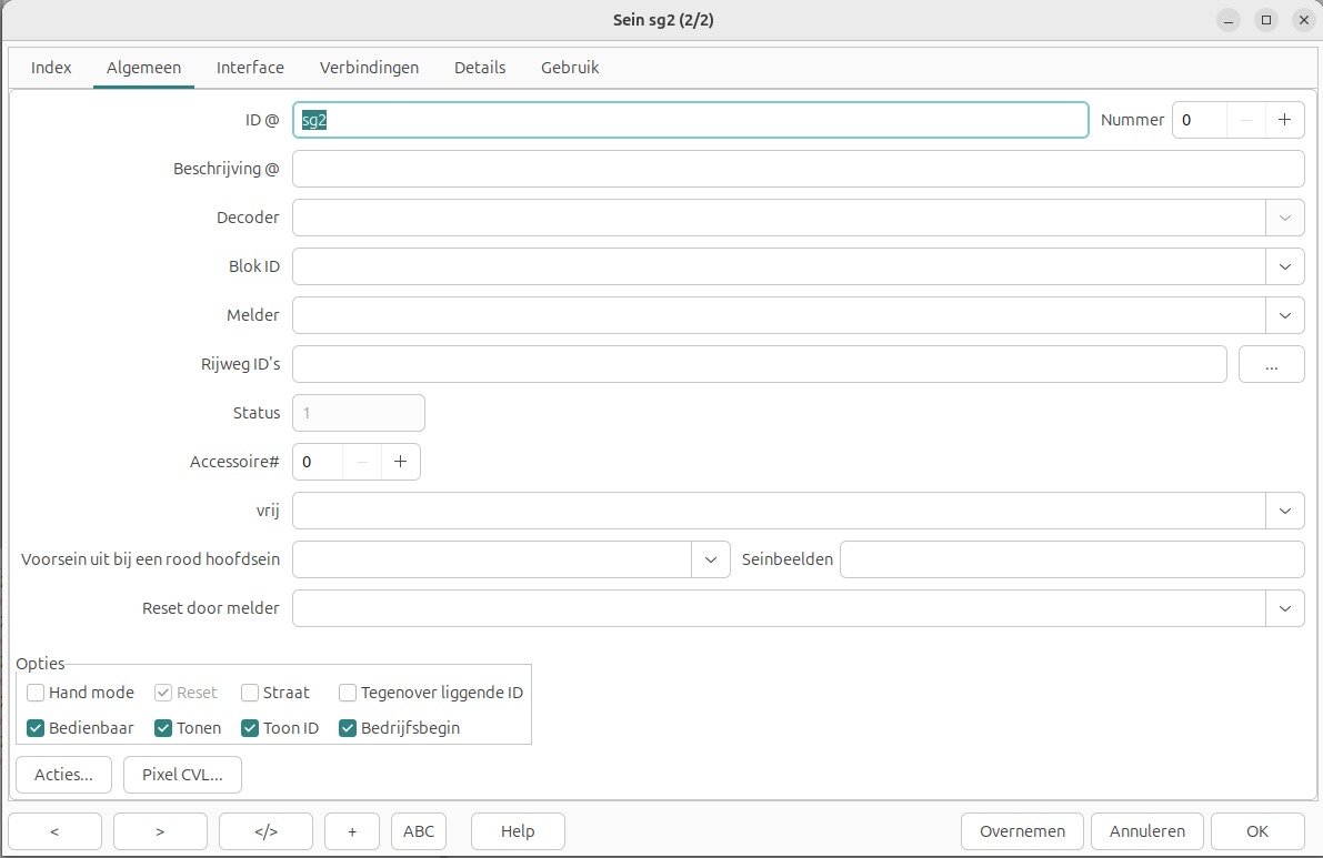
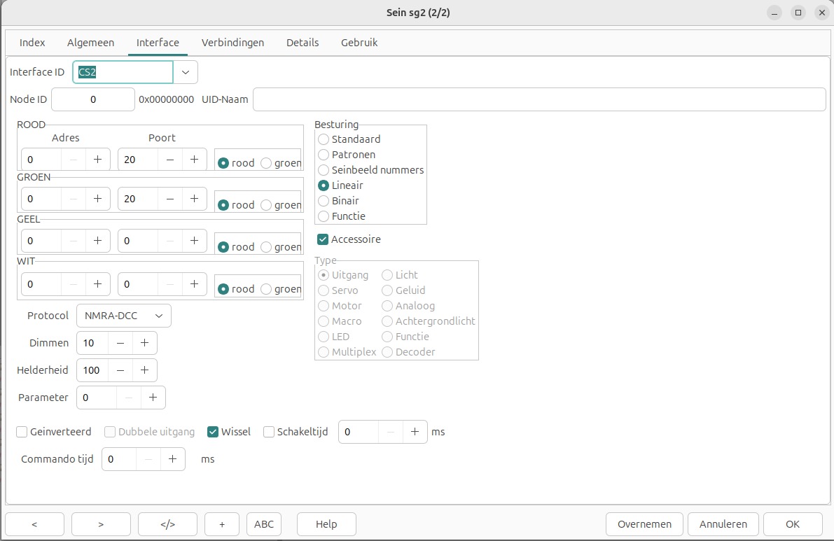
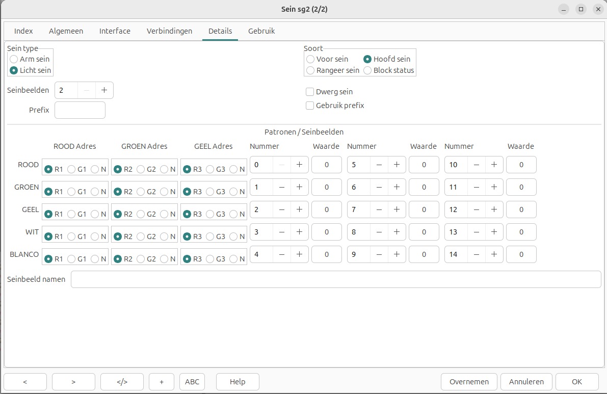
Natuurlijk moet er ook in CS2 een sein op adres 20 aangemaakt worden.