Op een modelspoorbaan is het handig/nodig om te weten waar, in welk blok, een loc zich bevind. Märklin levert hiervoor de S88 detectiemodules. Zie hiervoor: Terugmelding met S88 modules. Op mijn baantje is de detectie geregeld met een Arduino en een paar OKKIEs van de firma Arcomora.
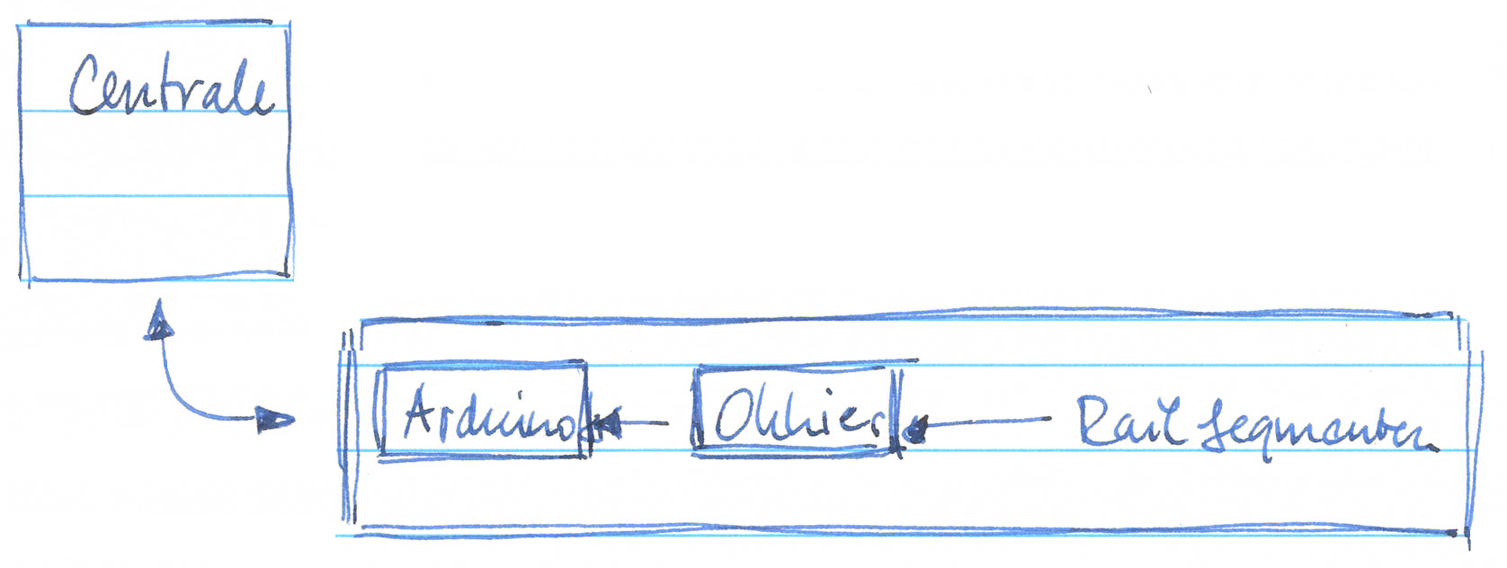
De baan is opgebouwd met een achttal blokken, waarvan er zeven in gebruik zijn. Elk blok heeft aan het begin en aan het einde een detectiesegment. Het deel daartussen is een ongedetecteerd segment.
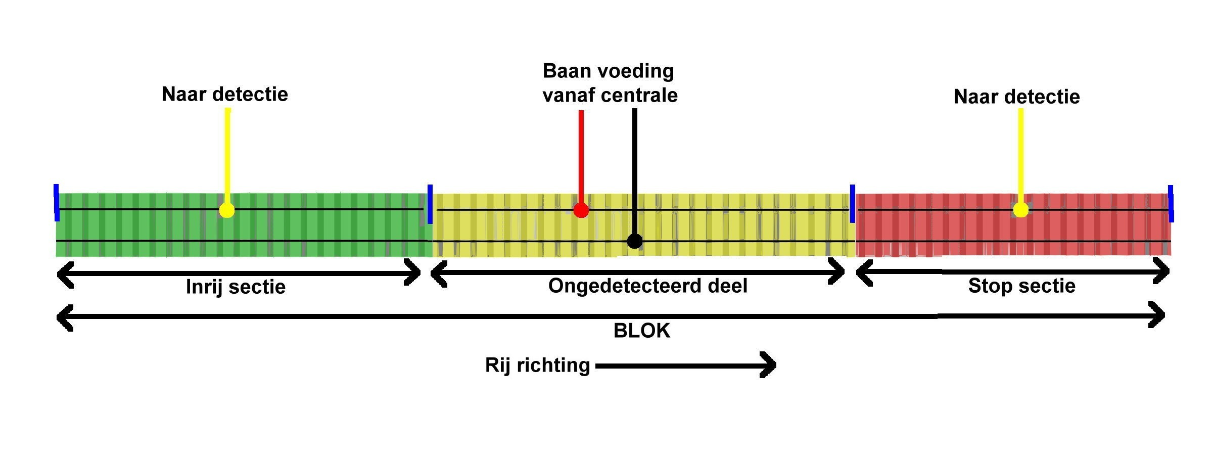
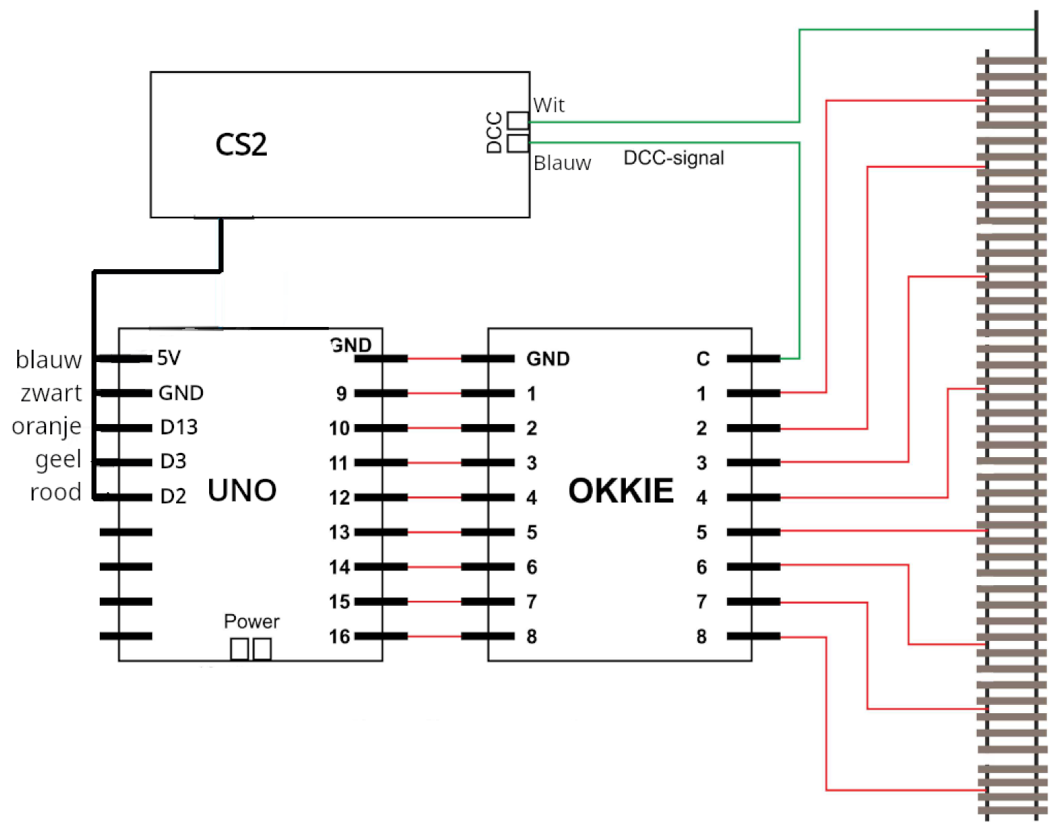
Elk segment (inrit en uitrit) wordt voorzien van een stukje detectie-elektronica. Een OKKIE bevat acht detectie-ingangen. Wanneer een loc (stroomafnemer) in het detectiesegment rijdt gaat de optocoupler (PC844) “geleiden” en zorgt voor een HOOG naar LAAG transitie op de uitgang van de schakeling. Zie hieronder het schema. Die transitie wordt gelezen door de Arduino, die vervolgens voor een bezetmelding naar de centrale zorgt.

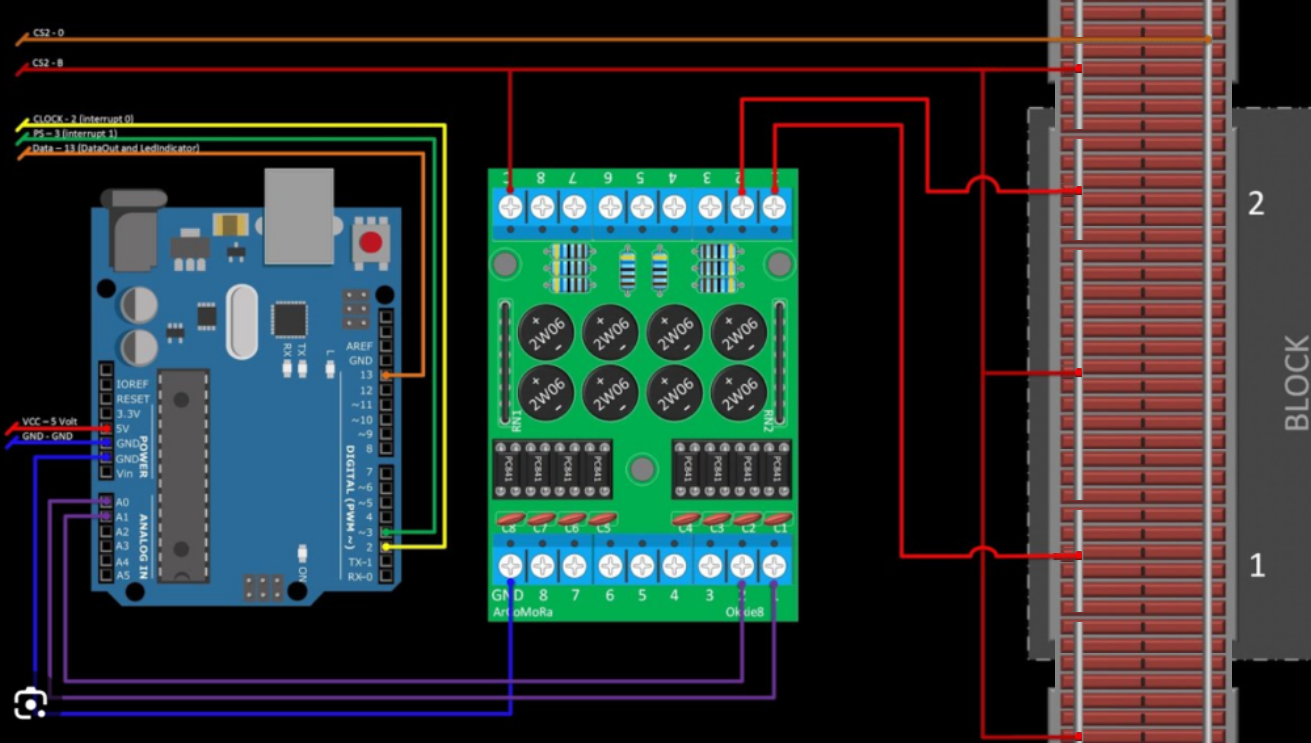
De acht uitgangen van elke OKKIE zijn daartoe verbonden met de twee maal acht ingangen op de Arduino UNO (A0 t/m A5, D0, D1, D4 t/m D11). Op de Arduino draait een sketch van Ruud Boer die de detectie informatie doorgeeft aan de centrale (zie hieronder).
/*
S88 occupancy sensor interface to the Märklin Central Station 2
Software by Ruud Boer, November 2014.
Freely distributable for private, non commercial, use.
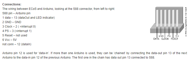
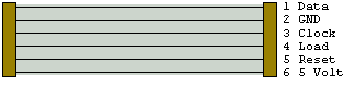
Connections for S88 bus:
s88 pin 1 Data - Arduino pin 13 = Data_Out to Oommand Station, or to the previous Arduino in the chain
s88 pin 2 GND - Arduino GND
s88 pin 3 Clock - Arduino pin 2, interrupt 0
s88 pin 4 PS - Arduino pin 3, interrupt 1
S66 pin 5 Reset (not used here) - Arduino pin 12, used as DATA IN from previous Arduino DATA OUT
s88 pin 6 V+ - Arduino 5V
IMPORTANT: To avoid S88 signals to jitter, it is best to put DATA_in pin 12 to GND on the last Arduino in the chain.
Connections for sensors: see table in void Setup() at line 35.
REMARK1: Inputs have the internal pullup resistor active, the sensors must pull the input to GND.
REMARK2: How short a pulse is allowed from the sensors before it is not seen?
A test showed that the main loop where all sensors are read runs once every 76 microseconds.
If a train runs over the reed switch with a speed of 1m/s, which is over 300 km/hr, that translates to 1 mm/ms.
So even if the reed switch would be on only for a 1 mm travel distance, then still the Arduino
will read that info more than 10 times!
*/
int clockCounter=0;
long loopCounter=0; //used in lines 55 and 88, see there for explanation
unsigned int sensors=0;
unsigned int data=0xffff;
const byte dataIn=12; //data input from next Arduino in S88 chain
const byte dataOut=13; //data output pin=13
boolean loadSensors=false; //flag that says to load sensor bits into dataOut bits
void setup() {
pinMode(2, INPUT_PULLUP);
attachInterrupt(0,clock,RISING); //pin 2 = clock interrupt
pinMode(3, INPUT_PULLUP);
attachInterrupt(1,PS,RISING); //pin 3 = PS interrupt
pinMode(dataIn,INPUT_PULLUP); //pin 12 = data in from next Arduino S88 in chain
pinMode(dataOut, OUTPUT); //pin 13 = data out to ECoS or to previous Arduino in S88 chain
digitalWrite(dataOut, LOW); //LED off
pinMode(A0, INPUT_PULLUP); //sensor 01
pinMode(A1, INPUT_PULLUP); //sensor 02
pinMode(A2, INPUT_PULLUP); //sensor 03
pinMode(A3, INPUT_PULLUP); //sensor 04
pinMode(A4, INPUT_PULLUP); //sensor 05
pinMode(A5, INPUT_PULLUP); //sensor 06
pinMode(0, INPUT_PULLUP); //sensor 07
pinMode(1, INPUT_PULLUP); //sensor 08
pinMode(4, INPUT_PULLUP); //sensor 09
pinMode(5, INPUT_PULLUP); //sensor 10
pinMode(6, INPUT_PULLUP); //sensor 11
pinMode(7, INPUT_PULLUP); //sensor 12
pinMode(8, INPUT_PULLUP); //sensor 13
pinMode(9, INPUT_PULLUP); //sensor 14
pinMode(10, INPUT_PULLUP); //sensor 15
pinMode(11, INPUT_PULLUP); //sensor 16
}
void loop() {
if (loopCounter==600){bitSet(sensors,0);}
/*
For an unknown reason the ECoS sets the first 8 bits to 1 after startup / reset of the S88 Arduino's.
When one of the sensor inputs is changed, from there on everything goes well.
Therefore, over here we give sensor bit 0 an automatic change after 30 seconds, when the ECoS is fully started.
The 1 second is created via 'loopCounter', which increments in the PS interrupt (line 88).
There are appr0ximately 20 PS pulses per second, therefore we use 20x30=600 in the if statement.
*/
if (!digitalRead(A0)) {bitSet(sensors,0);}
if (!digitalRead(A1)) {bitSet(sensors,1);}
if (!digitalRead(A2)) {bitSet(sensors,2);}
if (!digitalRead(A3)) {bitSet(sensors,3);}
if (!digitalRead(A4)) {bitSet(sensors,4);}
if (!digitalRead(A5)) {bitSet(sensors,5);}
if (!digitalRead(0)) {bitSet(sensors,6);}
if (!digitalRead(1)) {bitSet(sensors,7);}
if (!digitalRead(4)) {bitSet(sensors,8);}
if (!digitalRead(5)) {bitSet(sensors,9);}
if (!digitalRead(6)) {bitSet(sensors,10);}
if (!digitalRead(7)) {bitSet(sensors,11);}
if (!digitalRead(8)) {bitSet(sensors,12);}
if (!digitalRead(9)) {bitSet(sensors,13);}
if (!digitalRead(10)) {bitSet(sensors,14);}
if (!digitalRead(11)) {bitSet(sensors,15);}
}
void PS() {
clockCounter=0;
data=sensors;
sensors=0;
loopCounter++; //Increment loopCounter to cretae a timer. See line 55 for explanation.
}
void clock() {
digitalWrite(dataOut,bitRead(data,clockCounter));
delayMicroseconds(16); //Delay makes reading output signal from next Arduino in chain more reliable.
bitWrite(data,clockCounter,digitalRead(dataIn));
clockCounter =(clockCounter +1) % 16;
}
De connectie vanaf de Arduino naar de centrale is een seriële verbinding. De aansluiting hiervoor vind je op de CS2 aan de onderkant.
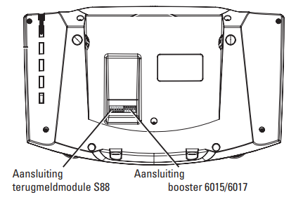
Bij het baantje geleverde snoertje tussen de CS2 en de Arduino ziet er als volgt uit.
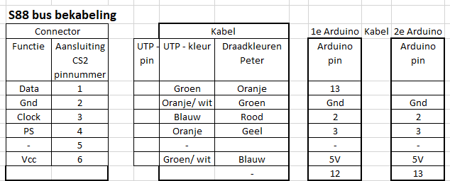
Het kabeltje heeft aan de ene kant een 6-polige JST male connector en aan de andere kant een male UTP45 aansluiting. Die laatste past in een female UTP45 aansluiting in de zijkant van de modelbaan. Van daaruit gaat een UTP kabel naar de Arduino.