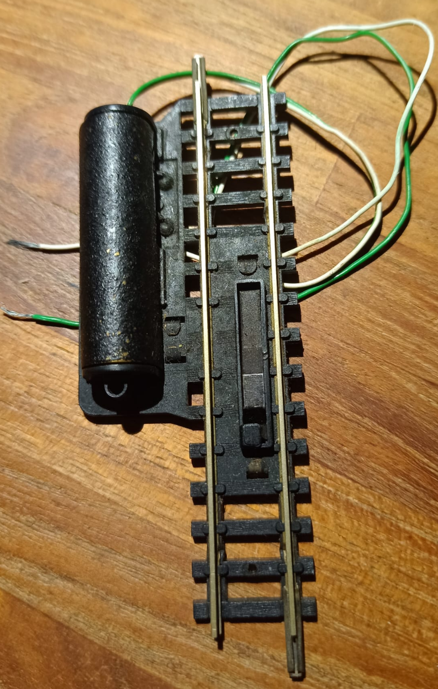
In een eerder deel (deel 7) heb ik beschreven hoe middels de combinatie Arduino en de MOSFET-module wissels omgezet kunnen worden. Deze MOSFET-modules kunnen ook gebruikt worden om bijvoorbeeld ontkoppelrails aan te sturen. Hiervoor gebruiken we weer de DCC Accessory sketch (zie hieronder).
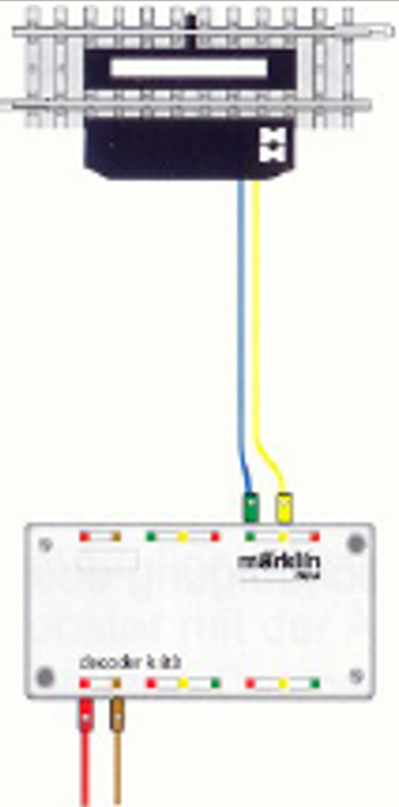
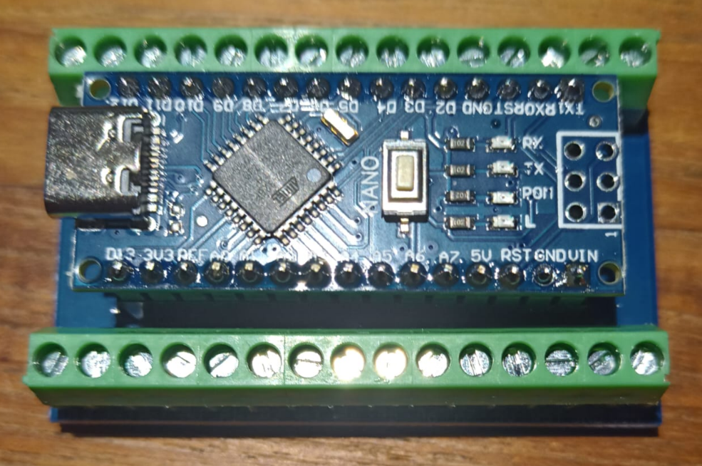
In dit geval wordt de hierboven getoonde K-83 vervangen door de Arduino en MOSFET-module.
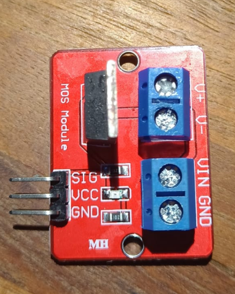
IRF520-module
//////////////////////////////////////////////////////////////////////////////////////////////////////////////////////
// DCC Accessory / Function Decoder
// Author: Ruud Boer - September 2015
// This sketch turns an Arduino into a DCC decoder with max 17 function outputs.
// Output pins used: 3-19 (14-19 = A0-A5). Pin becomes LOW when accessory is switched ON
// Modes: 1-continuous, 2=oneshot, 3=flasher with 2 alternatin outputs, 4=signal with 2 inverted outputs
// The DCC signal is fed to pin 2 (=Interrupt 0).
// Optocoupler schematics for DCC to 5V conversion: www.rudysmodelrailway.wordpress.com/software
// Many thanks to www.mynabay.com for publishing their DCC monitor and -decoder code.
//////////////////////////////////////////////////////////////////////////////////////////////////////////////////////

//////////////////////////////////////////////////////////////////////////////////////////////////////////////////////
// IMPORTANT: GOTO lines 20 and 43 to configure some data!
//////////////////////////////////////////////////////////////////////////////////////////////////////////////////////

#include <DCC_Decoder.h>
#define kDCC_INTERRUPT 0

//////////////////////////////////////////////////////////////////////////////////////////////////////////////////////
// Fill in the number of accessories / functions you want to control
//////////////////////////////////////////////////////////////////////////////////////////////////////////////////////
const byte maxaccessories = 4;
//////////////////////////////////////////////////////////////////////////////////////////////////////////////////////

typedef struct {
  int               address;          // User Configurable. DCC address to respond to
  byte              mode;             // User Configurable. Mode: 1=Continuous, 2=Oneshot, 3=Flasher
  byte              outputPin;        // User Configurable. Arduino pin where accessory is connected to
  byte              outputPin2;       // User Configurable. 2nd pin for AlternatingFlasher (e.g. railway crossing)
  int               ontime;           // User Configurable. Oneshot or Flasher on time in ms
  int               offtime;          // User Configurable. Flasher off time in ms
  byte              onoff;            // User Configurable. Initial state of accessory output: 1=on, 0=off (ON = pin LOW)
  byte              onoff2;           // User Configurable. Initial  state of 2nd output: 1=on, 0=off
  byte              dccstate;         // Internal use. DCC state of accessory: 1=on, 0=off
  byte              finished;         // Internal use. Memory that says the Oneshot is finished
  unsigned long     onMilli;          // Internal use.
  unsigned long     offMilli;         // Internal use.
}
DCCAccessoryAddress;
DCCAccessoryAddress accessory[maxaccessories];

//////////////////////////////////////////////////////////////////////////////////////////////////////////////////////
// Fill in the attributes for every accessory / function
// COPY - PASTE as many times as you have functions. The amount must be same as in line 18 above!
//
//
//
//////////////////////////////////////////////////////////////////////////////////////////////////////////////////////
void ConfigureDecoderFunctions() // The amount of accessories must be same as in line 26 above!
{
  accessory[0].address = 50; // DCC address
  accessory[0].mode = 1; // Continuous: HIGH until DCC switches the address off again
  accessory[0].outputPin = 3; // Arduino pin to which this accessory is connected

  accessory[1].address = 51;
  accessory[1].mode = 2; // Oneshot: HIGH for ontime ms, then LOW and stays LOW.
  accessory[1].outputPin = 4;
  accessory[1].ontime = 1000;

  accessory[2].address = 52;
  accessory[2].mode = 3; // Flasher: HIGH for ontime ms, LOW for offtime ms, repeats till DCC off
  accessory[2].outputPin = 5;
  accessory[2].outputPin2 = 6; // Flasher can use 2 outputs, they will flash  on/off alternatively
  accessory[2].ontime = 500;
  accessory[2].offtime = 500;

  accessory[3].address = 53; // DCC address
  accessory[3].mode = 4; // Continuous: HIGH until DCC switches the address off again
  accessory[3].outputPin = 7; // Green signal
  accessory[3].outputPin2 = 8; // Red Signal
  accessory[3].onoff2 = 1; // Initially set Red signal to ON

}  // END ConfigureDecoderFunctions

  //////////////////////////////////////////////////////////////////////////////////////////////////////////////////////
  // DCC accessory packet handler
  //////////////////////////////////////////////////////////////////////////////////////////////////////////////////////
  void BasicAccDecoderPacket_Handler(int address, boolean activate, byte data)
  {
    // Convert NMRA packet address format to human address
    address -= 1;
    address *= 4;
    address += 1;
    address += (data & 0x06) >> 1;

    boolean enable = (data & 0x01) ? 1 : 0;

    for (int i=0; i<maxaccessories; i++)
    {
      if (address == accessory[i].address)
      {
        if (enable) accessory[i].dccstate = 1;
        else accessory[i].dccstate = 0;
      }
    }
  } //END BasicAccDecoderPacket_Handler

//////////////////////////////////////////////////////////////////////////////////////////////////////////////////////
// Setup (run once)
//////////////////////////////////////////////////////////////////////////////////////////////////////////////////////
void setup()
{
  ConfigureDecoderFunctions();
  DCC.SetBasicAccessoryDecoderPacketHandler(BasicAccDecoderPacket_Handler, true);
  DCC.SetupDecoder( 0x00, 0x00, kDCC_INTERRUPT );
  pinMode(2,INPUT_PULLUP); // Interrupt 0 with internal pull up resistor (can get rid of external 10k)

  for(int i=3; i<20; i++)
  {
    pinMode(i, OUTPUT);
    digitalWrite(i, LOW); //all function outputs are set to 0 at startup
  }
} // END setup

//////////////////////////////////////////////////////////////////////////////////////////////////////////////////////
// Main loop (run continuous)
//////////////////////////////////////////////////////////////////////////////////////////////////////////////////////
void loop()
{
  static int addr = 0;

  DCC.loop(); // Loop DCC library

  if( ++addr >= maxaccessories ) addr = 0; // Next address to test

  if (accessory[addr].dccstate)
  {
    switch (accessory[addr].mode)
    {
    case 1: // Continuous
      accessory[addr].onoff = 1;
      break;
    case 2: // Oneshot
      if (!accessory[addr].onoff && !accessory[addr].finished)
      {
        accessory[addr].onoff = 1;
        accessory[addr].offMilli = millis() + accessory[addr].ontime;
      }
      if (accessory[addr].onoff && millis() > accessory[addr].offMilli)
      {
        accessory[addr].onoff = 0;
        accessory[addr].finished = true; //this is reset to flase below in the 'else' statement
      }
      break;
    case 3: // Flasher, is always an 'alternating' flasher together with .outputPin2
      if (!accessory[addr].onoff && millis() > accessory[addr].onMilli)
      {
        accessory[addr].onoff = 1;
        accessory[addr].onoff2 = 0;
        accessory[addr].offMilli = millis() + accessory[addr].ontime;
      }
      if (accessory[addr].onoff && millis() > accessory[addr].offMilli)
      {
        accessory[addr].onoff = 0;
        accessory[addr].onoff2 = 1;
        accessory[addr].onMilli = millis() + accessory[addr].offtime;
      }
      break;
    case 4: // Signal
      accessory[addr].onoff = 1;
      accessory[addr].onoff2 = 0;
      break;
    }
  }
  else //accessory[addr].dccstate == 0
  {
    accessory[addr].onoff = 0;
    if (accessory[addr].mode == 4) accessory[addr].onoff2 = 1; else accessory[addr].onoff2 = 0;
    if (accessory[addr].mode == 2) accessory[addr].finished = false; // Oneshot finished by DCCstate, not by ontime
  }

  // activate outputpin, based on value of onoff
  if (accessory[addr].onoff) digitalWrite(accessory[addr].outputPin, LOW);
  else digitalWrite(accessory[addr].outputPin, HIGH);
  if (accessory[addr].onoff2) digitalWrite(accessory[addr].outputPin2, LOW);
  else digitalWrite(accessory[addr].outputPin2, HIGH);

} //END loop